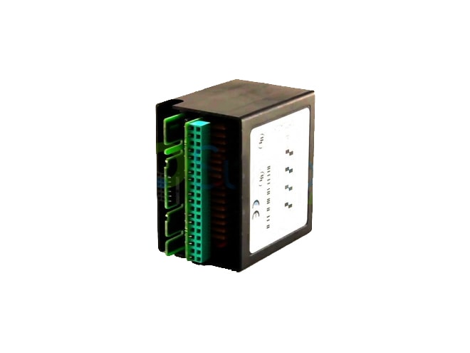
Remanufactured GE-Emerson IC670ALG620 Field Control RTD Analog Input Module
4 analog inputs (4 words).

Remanufactured
-
11 in stock
-
Additional 7 ready to ship within 2-3 days
- IC670ALG620RMN
- By GE-Emerson
Overview
Features
- Scan time:
- 60Hz: approx. 210 milliseconds per point
- 50Hz: approx. 230 milliseconds per point
- Fault detection:
- Open RTD
- Input short
- Underrange/overrange
- High/low alarm
- 60dB normal mode rejection at 50/60Hz, 100% span
- 120dB common mode rejection at 50/60Hz, 100ohm imbalance
- 250Vrms common mode voltage (350VDC or peak AC)
- Normal mode voltage:
- 100% overrange DC or peak AC operational
- 28VDC or peak AC max.
- Isolation:
- 1500VAC for 1 minute, 250VAC continuous user input to logic, user input to frame ground
- 250VAC continuous channel to channel
- 190mA max. current drawn from BIU power supply
- 15 bits plus sign digital resolution
- 32 to 131°F operating temperature range
Description
The GE-Emerson IC670ALG620 Field Control RTD Analog Input Module accepts inputs from four independent 3-wire and/or 4-wire platinum, nickel, nickel/iron, or copper RTDs.
No loop power is required for this module. The excitation current for the RTDs is provided by the module, which automatically matches the excitation current to each configured RTD type.
The module converts input levels to a digital value. Input spans support a variety of RTD types.
The analog/digital converter reads the voltage generated by each of the four inputs. The A/D converter converts the differential measurement into a binary value (15bits plus sign), which is read by the block's microprocessor. The microprocessor sets the gain required in the analog/digital converter for each individual input. The gain is based on the RTD type that has been configured for that input.
The microprocessor selects the input by means of a solid state, optically-coupled multiplexer. Three measurements are made for each input: excitation current, RTD resistance including field wire drop, and field wire drop. From these three measurements, the module calculates the RTD resistance. A DC/DC converter circuit isolates the field side from the logic circuits.
Documents
Need Help? Call an expert at 1-704-702-6380
We're open Mo-Fr 8:00am to 5:00pm


