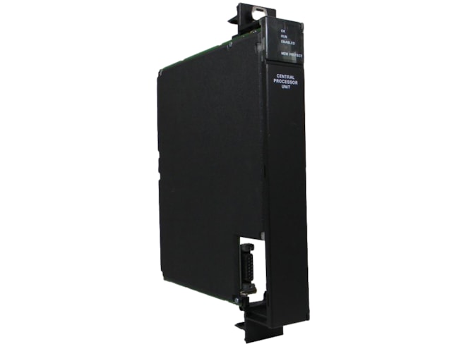
Repair GE-Emerson IC697CPU780 Series 90-70 Expandable Floating Point CPU
Required for hot standby CPU applications; 16MHz, 32-bit.

Remanufactured
-
3 in stock
-
Additional 4 ready to ship within 2-3 days
For on-site repair and support, call us at 1-704-448-2212 or email sales@qualitrol.com.
- IC697CPU780REP
- By GE-Emerson
Overview
Features
- Supports floating point calculation
- Single-slot
- 12k inputs and outputs (any mix)
- Up to 8k analog I/O
- 0.4 microseconds per Boolean function
- 80386DX microprocessor
- Supports IC660/IC661 and IC697 I/O products
- Programmed by MS-DOS-based software products
- Supports up to 512kb of battery-backed expansion memory in the same slot
- Configurable data and program memory
- Battery-backed calendar clock
- Three-position operation mode switch
- Password-controlled access
- Keys with memory protection
- Four status LEDs
- Software configuration (no DIP switches or jumpers to set)
- Reference information inside the front door
- See datasheet for additional redundancy features
Description
The GE-Emerson IC697CPU780 Series 90-70 Expandable Floating Point CPU allows floating point calculations and is programmed and configured by IC641 programming software to perform real-time control of machines, processes, and material handling systems.
The CPU communicates with I/O and smart option modules over the rack-mounted backplane (IC697CHS750, 790, 791) by way of the VME C.1 Standard format.
Supported option modules include all IC697 LAN interface modules, several Coprocessor modules, Bus Controller for IC660/IC661 I/O, Communications modules, and all of the IC697 family of discrete and analog I/O modules.
Program and data memory for the CPU is available by the attachment of an expansion memory board with either 128kb, 256kb, or 512kb of battery-backed CMOS RAM, or 256kb with 256kb of non-volatile flash memory. These memory boards provide error checking through a CPU checksum routine with detected parity errors being reported to the CPU as they occur.
Operation of this module may be controlled by the three-position RUN/STOP switch or remotely by an attached programmer and IC641 software. Program and configuration data can be locked through software passwords or manually by the memory protect keyswitch. When the key is in the protected position, program, and configuration data can only be changed by a programmer connected through parallel communications (i.e., via the Bus Transmitter module). The status of the CPU is indicated by the four green LEDs on the front of the module.
The CPU 780 is used as the CPU in a Hot Standby CPU Redundancy system. Two CPUs are required in a Hot Standby CPU redundancy system; one in the Primary PLC and one in the Secondary PLC. Each of the CPUs must be configured separately, with one configured as the Primary unit and one configured as the Secondary unit.
Documents
Need Help? Call an expert at 1-704-702-6380
We're open Mo-Fr 8:00am to 5:00pm


